Detlef Aigner
Technische Universitaet Dresden, 01309 Germany
Tel +4935146334397 E-mail detlef@d-aigner.de
Abstract: Cascades and stepped chutes are used for the discharge of water over dams or steep slopes. These are sequentially placed drops which either enable the step by step dissipation of the hydraulic energy or overflow by skimming flow. The stepped transitions ensure a good aeration of the water as a result of which an air-water mixture type of flow takes place. If the steps are designed as small stilling basins to dissipate the energy, they are called pooled step cascades. The hydraulic design of these structures will be dealt with in this paper.
The advantages of pooled steps and stepped chutes are the stepwise reduction of kinetic energy of the water through transformation into heat, so that the size of the stilling basin can be reduced. They are preferably applied for dam spillways or combined sewer systems for the safe discharge of water over large drops.
Stepped chutes are often combined with the spillway of the dam. They are also used in parks and are suitable to the type of river course design improving natural surroundings.
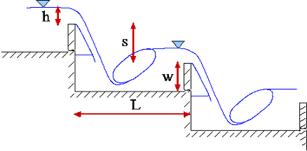
Each step in a pooled step cascade corresponds to on isolated stilling basin (Fig. 1) for hydraulic jump. On stepped chutes the water falls from level to level and the optimal dissipation is expected if a hydraulic jump builds. For steeper stepped chutes and large discharges, so called skimming flow occurs in which the step acts as roughness element and causes a strong mixing of the water with air.
Most research
work has been conducted with flat horizontal steps, and there is little work on
pooled steps. Press (1954) wrote in his book stauanlagen und Wasserkraft
(reservoirs and water energy) that the use of cascades as energy dissipaters was
neglected because the structures are highly susceptible to the effects of ice
and weathering. Recent publications and the international workshop in Zurich
(March 2000 in Switzerland) indicate that interest in hydraulics of stepped
spillways has significantly increased in the past years.
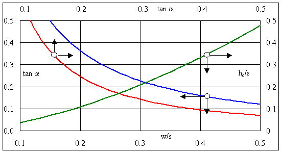
Fig. 2 enables
the calculation of the minimum dimension of pooled steps (full energy
dissipation) considering a safety
addition of 5% for the conjugate depth and the minimum length of one step. The
design underlies the following principal equations for the two-dimensional
calculations.
Definition of
parameters:
s height of step hc
critical depth
h water level of overflow
h1,2 sequent
depths of hydraulic jump
L length of step
Lp
jet impact position
w height of weir step
Lj length of
hydraulic jump
q specific discharge
Cd discharge
coefficient
v velocity
g gravitational constant
The slope of pooled steps is calculated as the ratio of the step height
and the step length, including the thickness of the weir wall
![]() (1)
(1)
The critical depth hc is
used as an auxiliary variable to represent the specific discharge as
 (2)
(2)
The specific discharge is calculated with a standard overflow formula.
The discharge coefficient Cd (for the case of a sharp-crested weir, Bollrich 2000) should include the effect of approach velocity.
![]() (3)
(3)
 (4)
(4)
The velocity (v1) at
the downstream end of the jet is calculated from the energy equations as
(without loss of energy)
 (5)
(5)
![]() (6)
(6)
The hydraulic jump is assumed to develop fully and calculated with the conjugate depth equation (Bollrich 2000)
 (7)
(7)
The height of the weir w plus a
5% safety margin for h2 amounts to
![]() (8)
(8)
The length L of a step required
is determined based on the so called throw length of the jet Lt according to Oficerow (Bollrich,
2000) and the necessary length of a hydraulic jump Lw according to U.S.B.R..
There is further possibility of optimising the length, for instance, through the
minimize the length of the jet.
![]() (9)
(9)
![]() (10)
(10)
![]() (11)
(11)
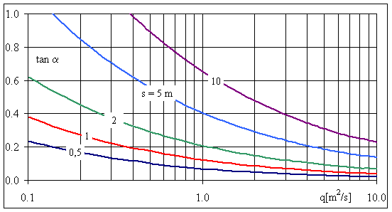
The above described equations allow to design pooled step cascades with full hydraulic jump. Figs. 2 and 3 illustrate the results.
Example
Given a dam
with a height of H = 10 m and an
inclination of tana =
0.15, develop a pooled step cascade with a selected height of s = 1 m and number of levels N = 10 in order to convey a discharge of
5 m³/s.
Figure 3: tana = 0.15 q = 0.6 m2/s
b = Q/q
= 5/0.6 = 8.33 m
Figure 2: tana = 0.15 w/s =
0.41 w = 0.41 m
tana = 0.15 L = s/tana = 1/0.15= 6.7 m
The values obtained are nearly the same, if the discharge is determined with the critical depth.
control: hc
= (q2/g)1/3 = 0.332 m
hc/s = 0.332 w/s
= 0.41
The height, length and width of the pooled step cascade are easily and quickly determined to have values of 0.41 m, 6.7 m, and 8.33 m respectively. With rounded overfall (close-lying jet) the length of basin according to shortened by approximately 25%.
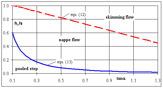
Basically two
types of overflow are differentiated, the nappe flow and the skimming flow. The
transition between the two types of regimes can be determined by Chanson (1994b)
simplified equation
![]() (12)
(12)
Nappe flow is differentiated between stepped chutes without and pooled
step with hydraulic jump. The sizing of pooled step cascades is an approximation
to the result in Figs. 2 and 3. The limits of application for a cascade with
fully developed hydraulic jump can be estimated with equation (13). The use of
cascades above the limits of this equation results is without hydraulic jump and
the kinetic energy hand over to the next basin.
 (13)
(13)
For stepped
chutes (w = 0) a large number of levels and a higher roughness produce a better
energy conversion (Chanson, 1994a). The strongly aerated skimming flow achieves
a better energy dissipation than the nappe flow.
The maximum
possible energy dissipation can theoretically be determined with the assumption
that the total dam H is converted to
energy head through the overcoming of cascades. The energy dissipation is
referred to as DH. The
degree of dissipation (the energy dissipation related to the maximum possible
energy height Hmax) is
expressed as a function of the ratio of the height H and the critical depth hc.
For cascades, for example, the maximum energy dissipation is
![]() (14)
(14)
The energy conversion
with stepped chutes always lies under this limiting curve. The analysis of
Chanson (1994a), Mates and Quintela (1995) shows results of extensive
experiments of different authors. The friction coefficient has, for example, a
large influence on the calculation of the energy dissipation with skimming flow.
With nappe type flow, the number of levels have an important role and the
friction influence is not represented here.
Investigation in the past years facilitated the possibility of designing cascades for discharging flood over dams and steep gradients. From literature, it appears that the empirical investigations were particularly done for stepped chutes. To supplement these works, the author examined the limits of application of pooled step cascades and compared these with the results for stepped chutes. The outcome was the development of a simple and quick technique which enables the design of pooled steps and the comparison of these with stepped chutes.
References
[1]
Bollrich, G. (2000). Technische
Hydromechanik, Band 1, 4. Auflage, Verlag fur Bauwesen Berlin (in German).
[2]
Chanson, H. (1994a). Comparison of energy dissipation
between nappe and skimming flow regimes on stepped chutes. Journal of Hydraulic
Research 32, S. 213-218.
[3]
Chanson, H. (1994b). Hydraulics of skimming flow over
stepped channels and spillways. Journal of Hydraulic Research 32, S. 445-460.
[4] Matos, J.; Quintela, A. (1994). Discussion for paper of Chanson (1994a and b) in Journal of Hydraulic Research 32, S. 135-139.
[5] Press, H. (1954). Stauanlagen und Wasserkraft. II Teil: Wehre. W. Ernst & Sohn, Berlin (in German).

Fig. 1 Pooled step cascade

Fig. 2 Design of pooled step cascades

Fig. 3 Inclination of pooled step cascade

Fig. 4 Boundary between nappe flow and skimming flow over a stepped chutes and between overflow of pooled step cascades with and without hydraulic jump